2016 Mini-Kit Thread (B&O M-15k)

Mike

Administrator
Staff member
M-15k-03.JPG


This year, RPM Chicagoland is bringing back the Mini-Kit concept. The Mini-Kit, back in the Sunshine Models days, was a gift to attendees of the annual "Naperville" conference, and included a small set of resin parts, decals, or other items that would be used to convert a readily available plastic model into a different prototype.

This year, through the generosity of Fox Valley Models, Resin Car Works, Accurail, Micro-Trains, Tom Madden and Ted Cullota, a complete kit with conversion parts and the base model was available to the first 200 registrants in HO and 50 more in N scale.

This thread is here to share information on the prototype B&O M-15k class cars, and allow builders to share their progress as we lead up to the 2017 RPM Conference where we can all share our finished models!
 

Mike

Administrator
Staff member
Frank Hodina, the man behind Resin Car Works and lead on this year's Mini-Kit, will be available at the RCW booth in the vendor room to discuss this conversion. While full info sheets will be printed in the attendee program this year, you can see in progress and finished conversions, and get tips from Frank on how to perform the conversion.
 

Mike

Administrator
Staff member
Now that everyone is recovered from the conference, it's time to get started on the Mini-Kits!

I started my car by cutting the sill out of the bottom of the stock FVM M-53 shell. First I scribed a line just below the rivet line horizontally across the car, then free handed the vertical cuts. You don't need to cut all the way through with the knife - the styrene will cleanly snap just like you were working with Evergreen stock.

IMG_5065.JPG
IMG_5069.JPG
 

Mike

Administrator
Staff member
You'll need two long pieces of the thicker styrene strips included, and then a bunch of smaller pieces, in order to add thickness to the added framework tying the new M-15k body to the old fishbelly underframe. I cut the small bits longer than needed on a chopper:
IMG_5071.JPG


Cut two longer pieces to fill in the grove above the tabs and glued them in first. (These should like up with the cut you made to the side sill previously):
IMG_5072.JPG


Then glued the smaller pieces behind the tabs:
IMG_5073.JPG


Then clipped them to the right length after they were glued in. I avoid measuring where I can, so leaving them a bit long and trimming later is easiest:
IMG_5074.JPG
 
Last edited:

Jerry Hamsmith

New Member
Frank Hodina, the man behind Resin Car Works and lead on this year's Mini-Kit, will be available at the RCW booth in the vendor room to discuss this conversion. While full info sheets will be printed in the attendee program this year, you can see in progress and finished conversions, and get tips from Frank on how to perform the conversion.
This is a joint post from Jerry Hamsmith and Chris Vanko. We started on the build and thought we would share a few observations.

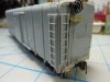
When preparing the body for the removal of the material along the sides between the ribs, it may or may not be best to install the backing styrene strips first. For the first car we did, we installed the strips as per the RPM handout. After first removing the sill steps as well as the 3 tabs on each inside of the body sides that were designed to hold in the floor, two strips of .040 x .100 styrene were cut to a length of 5-5/8", test fit, slightly sanded as needed and glued up against the floor stops. Small pieces of the same material were cut to fit behind each of the side ribs as well.

Filing away the body material between the ribs was not a easy process. Although it was easy to remove the material form the car body itself it was slow going once we reached level of the backing material. Prototype photos that Jerry found (see list below) indicated that the rivet line at the now bottom of the sides did not exist on the prototype. So, although, as the RPM handout indicates, you should file to just below the rivet line when removing material, you should come back and sand off the rivets.

On the second car we did, we did not add the backing until after removing the material between the ribs. Also, .040 x .080 material seems to work better. Once we figure out how to post a photo, we will show where the build on these cars is to this point.

Sources of Prototype photos:

Culotta, Steam Era Freight Cars Refernce Manual, Volume 1, Page 140 - Car number 371015
Kline and Cullota, The Postwar Freight Car Fleet, Page 75 - Cars 370261 and 371031
Wider, Railway Prototype Cyclopedia, Volume 9, Pages 9 and 10 - Cars 370577, 370853, 370974

Jerry and Chris
 
Last edited:

Mike

Administrator
Staff member
Good notes guys, you'll see my method of removing the material above which goes pretty quick.

Posting photos is easy as you can upload a file right to the post. You have the option to insert it as a thumbnail or full size after it is uploaded to the post.

There's also a couple variations of ladders and door stops to watch for in the prototype photos. There is a short ladder with two extra grab irons at the top, and a tall ladder with single grab variation. The latter matches the M-53 style ladders included. The other is an interesting variation that can be modeled. Also, at least one car in the handout (The lead photo from Bob's Photos) has a second door stop above the first.

Mike
 

Mike

Administrator
Staff member
Clip-of-George-Sisk-Photo-of-Sill.JPG


This is a clip of the George Sisk photo of 370853 from the RPM handout. It is lit well enough to show that the rivet line should be removed as Jerry and Chris noted above. You can also see that there is more detail of a flange and rivets in the shadows, where each rib is connected at the underframe, that can be added. Some .005" styrene and pairs of Archer rivets should be doable.
 

Mike

Administrator
Staff member
B&O 371031 - Tall ladder and single stop (This matches the M-53 parts)
Clip-of-Bob-Charles-Photo-371031.JPG


B&O 370577 - Short ladder and two door stops
Clip-of-Bobs-Photo-370577.JPG


B&O 370853 - Short ladder and single door stop
Clip-of-George-Sisk-Photo-of-370853.JPG
 

Jerry Hamsmith

New Member
Another post to show the progress on the Mini-Kit build.

As noted in my previous post, the backing was added to the car sides and then the material removed. I would not do this again – it is much easier to remove the material before adding the backing. See Mike’s post above for the better way. Also, I found that .040 x .080 material was a better size for the backing at the bottom of the car sides as well as behind the vertical body braces. Much less sanding would be needed if that size would have been used. Here is a photo of the inside of the car showing the backing, the .015 x .188 pieces, the new floor guides and the end guides I installed.

JDH Modified body sills.JPG


And here is how the side of the body looks after the addition of all of that. I also sanded off the lower rivet line as it was not present on the prototype.

JDH side after cut outs.JPG


More to come.

Jerry Hamsmith
 

Jerry Hamsmith

New Member
I moved on to the underframe next. I did things a little differently than mentioned in the very basic instructions provided in the RPM handout. I used .040 x .040 on the ends of the Accurail underframe to “lengthen” it. I also used a Cal-Scale AB brake set and did some of the basic brake system piping. For the coupler pockets, I removed the post and shortened the wings on the Accurail coupler bases and added the FVM kit coupler pockets and screws. These pockets were removed from the FVM underframe and their bottoms sanded smooth. The Accurail wings were cut back so these pockets would extend to the very end of the lengthened frame. Here is a photo with one end completed and a KD #5 installed.

JDH underframe.JPG


Jerry Hamsmith
 
Last edited:

Jerry Hamsmith

New Member
Finally finished the ends. Here is the B end. The holes for the end sill grabs were filled in as the new extended end sill would have grabs to replace them. I then attached the cast resin end.

JDH B end.JPG

I added the grabs and ladders provided in the kit to the ends as appropriate. Per the prototype photos, I used an Intermountain early Ajax brake wheel. The one included in the kit is a late Ajax wheel.

Also, the retainer pipe provided in the kit has a jog in it and prototype photos show a straight one. Mine is .008 brass and the valve is from the Cal Scale AB set. I cut off the kit provided brake staff just below the chain and added a new brake stem made from floral wire.

Jerry Hamsmith
 
Last edited:

Jerry Hamsmith

New Member
Just a quick post to show some completed cars.

model B&O 371031 Hamsmith.JPG


This is my model - completed to represent a car in use in 1955.

model B&O 370853 Vanko.JPG


Here is one completed by Chris Vanko. The basic paint color on each of these cars is the same - the weathering (oils and powders) makes them look different.

model B&O 371015 Vanko.JPG


Here is a second car Chris did.

Jerry Hamsmith
 

Mike

Administrator
Staff member
Great models guys!

I finally threw some Tru-Color paint on my model this past weekend, and am currently applying decals. I know... no photos-no proof!
 

George Toman

New Member
Here is a photo of my work in progress M-15k . Getting close to paint. Need to fix a broken rung.
George Toman
 

Attachments

  • P1040069 - Copy.JPG
    P1040069 - Copy.JPG
    250.4 KB · Views: 543

George Toman

New Member
Thanks Mike. I have some 40 plus year old Swiss Pattern files, # 6 fine. These are fairly small at about 4.5 inch long. These are very sharp for being a #6 cut
These are available but getting harder to locate. I have both Grobet-Swiss and Nicholson
George
 

Mike

Administrator
Staff member
Great looking car George!

For sake of interchange service, the couple may need to be flipped though... ;-)
 
K

Ken O'Brien

Guest
Any chance the resin parts for the mini-kit will be re done. Or could someone pass on the dimensions of the end beams? I'd like to give it a shot. Currently working up a Winston-Salem meet SOU ventilated boxcar.
 
Top